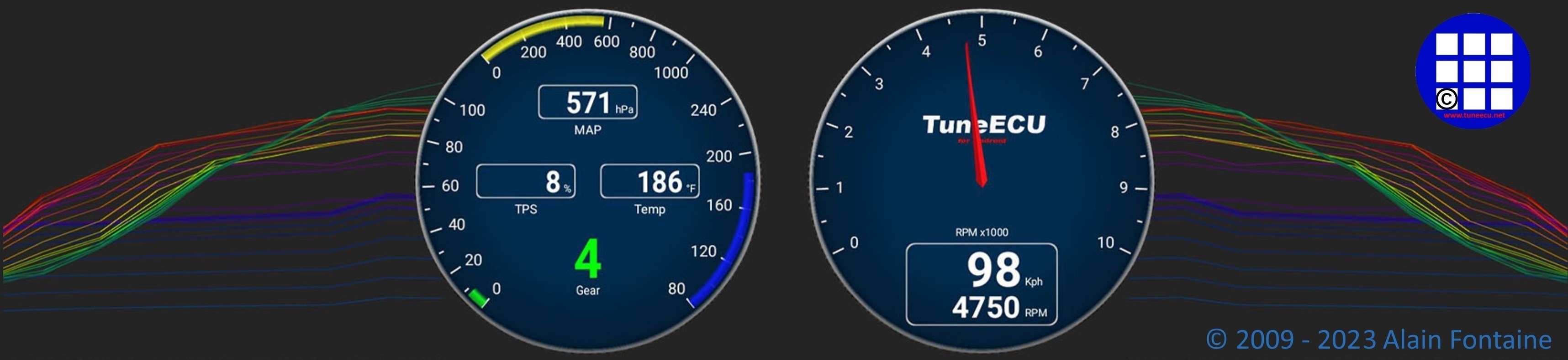
Moteur Système de Gestion de l'information
No Motobike Manufactor have had involvement in this product.
The use of a manufactures name and / or model designation to describe
the motorcycles on this site does not imply that the manufacturer endorses
the use of this application.
Jump to: - Capteurs Actionneurs
.
Description
du système (Rocket
III)
.Goto
Speed
Triple 885cc & 955cc modèles 1997 - 2001 Goto
The Rocket III is fitted with an electronic
engine management system
which encompasses control of
both ignition and fuel
delivery. The electronic control module (ECM)
draws information from Sensors
positioned around the engine,
cooling and air intake Systems and
precisely calculates ignition advance and fueling requirements for all
engine
speeds and loads.
occur in the engine management system, the malfunction type, and engine data at the time the
malfunction occurred, are stored in the ECM memory.
This stored data can then be recovered using a special Service tool which is mandatory for all Triumph dealers.
In this way, precise diagnosis of a fault can be made and the fault quickly rectified.
System Sensors
lntake air temperature sensor - situated at the front of the intake duct, above
the
cam cover.
As the density of the air (and therefore the amount of oxygen available
to
ignite the fuel) changes
with temperature, an intake air temperature
sensor is fitted. Changes in
air temperature (and
there fore air density) are compensated
for by adjusting the amount of
fuel injected to a level
consistent with clean combustion
and low emissions.
The barometric pressure sensor measures atmospheric air pressure. With
this
information
the amount of fuel per injection is adjusted to
suit the prevailing
conditions.
Manifold Absolute Pressure (MAP) sensor - situated at the front of the intake duct, above
the
cam cover, connected to each of the three throttle
bodies by equal
length tubes.
The MAP sensor provides information to the €CM which is used at shallow
throttle angles (very small
throttle openings) to provide
accurate engine load indications to the
€CM. This degree of
engine load accuracy allows the ECM to
make very small adjustments to
fuel and ignition which
would otherwise not be possible from
throttle angle data alone.
Clutch switch - situated on the clutch lever.
The clutch must be pulled in for the Starter motor to operate.
Crankshaft position sensor- situated in the alternator cover.
The crankshaft position sensor detects movement of a toothed wheel
attached tothe alternator rotor.
The toothed wheel gives a
reference point from which the actual
crankshaft position iscalculated.
The crankshaft position
sensor information is used by the
ECM to determine engine speed and crankshaft position in relation to
the point where fuel
is injected and ignition of the fuel occurs.
Engine coolant temperature sensor – situated towards the front of the cylinder
head, on
the left hand side.
Coolant temperature information, received by the ECM, is used to
optimise
fueling at all engine temperatures and to calculate hot and cold Start
fueling
requirements.
Primary throttle position sensor - situated at the rear of the lower throttle
spindle.
Used to relay throttle position information to the ECM. Throttle
opening angle
is used by the ECM to
determine fueling and ignition
requirements for all throttle positions.
Secondary throttle position sensor – situated at the front
of the upper throttle spindle.
Used to relay secondary throttle position information to the ECM.
Secondary
throttle angle is used by
the ECM to determine secondary
throttle opening position under all
engine running conditions.
Road speed sensor - situated in the lower crankcase. on the left
hand side.
The road speed sensor provides the ECM with data from which road speed
is
calculated and displayed on the speedometer. A vehicle speed limitation
device
also receives information from the
road speed
sensor.
Lambda sensor - situated in the exhaust header system upstream
of the catalyst box.
The lambda sensor constantly feeds information to the ECM on the
content of the
exhaust gases.
Based on this information, adjustments to
air/fuel ratio are made.
the engine will not run unless the transmission is in neutral.
System Actuators
n
response to
Signals received from the Sensors, the ECM controls and directs
messages to a
series of electronic and electro-mechanical actuators. The function and
location of the actuators is given below.
Primary
throttle stepper motor
- situated at
the front of the throttle bodies.
The primary throttle stepper actuates a cam lever which causes
variations in
the closed throttle position.
Although used
primarily to ensure target idle speed is maintained, it also increases
throttle opening when
the engine is cold.
Second throttle stepper motor
– situated between
the throttle bodies for numbers one and two cylinders.
In response to direction from the ECM, the second throttle
stepper motor movesthe second
throttle spindle
to the position directed by the ECM. The
second butterfly optimises
engine torque by maintaining intake
air flow speed. It
does not act as a choke
for cold Start
purposes.
Canister purge valve
(California models only) -
situated in the vapour return line between the
carbon
canister and the throttle bodies.
The purge valve controls the return of vapour which has been stored in
the
carbon canister during the period when the engine is switched off. The
valve is
'pulsed' by the ECM to give control over the rate at which the canister
is
purged.
lnjectors
- located in the throttle body assembly.
The engine is
fitted with three injectors. The Spray Pattern of the injectors is
fixed but
the length of time
each injector can remain Open is variable according to operating
conditions.
The duration of each injection is calculated by the ECM using data
received
from the various sensors in the
system.
lgnition coils
- mounted on a bracket, above the cam cover.
There are three coils fitted, one for each pair of spark plugs. The ECM
controls the point at which
the coils are switched on and off.
In calculating
the switch-on time, the ECM allows sufficient time for the coils to
charge to a
level where a spark
can be produced. The coils are switched off at the point of
ignition, the
timing of which is optimised
for good engine performance.
Fall detection switch
- situated behind the left hand
side cover.
The fall detection switch will detect if the motorcycle is on its side
and will
cut power to the ECM immediately.
This prevents the engine
from running and the
fuel pump from delivering fuel. In the event of a fall, the switch is
reset by
returning the bike to an upright position and switching the ignition
off then
back on again.
Main power relay
- situated behind the left hand side cover.
When the ignition is switched on, the main power relay is powered up to
provide
a stable voltage
supply for the ECM.
Fuel pump
- located inside the fuel tank.
The electric pump delivers fuel into the fuel System, via a pressure
regulator,
at a constant 3 bar pressure.
The
pump is run continuously when the engine is operating and is also run
briefly when the
ignition is first
switched on to ensure that 3 bar is
available to the system
as soon as the engine is
cranked. Fuel pressure is controlled by a regulator also situated
inside the fuel
tank.
Cooling fan
- located behind the radiator.
The ECM controls switching on and off of the cooling fan in response to
a
Signal received from the coolant temperature Sensor. When the coolant
temperature
rises to a level where the cooling effect of natural airflow is
insufficient,
the cooling fan is turned on by the ECM. When the coolant temperature
falls
sufficiently, the ECM turns the cooling fan off. The fan only becomes
operational
when the engine is running. It will not operate at any other time.
Note:
In this system, the Starter lockout system
(clutch switch, neutral
switch, sidestand
Supplement
Rocket III Roadster
Brakes
Anti-lock
Brake
System <ABS>
System Description
The
Rocket Ill Roadster is fitted with an
electronic anti-lock brake system which is designed to prevent
the wheels from
lockingor skidding by reducing braking effort to the front or rear
brake
caliper when
wheel lock is sensed.
The
system consists of a hydraulic
modulator and electronic control module <ECMl assembly mounted
to a bracket near the exhaust system link box,
a front wheel speed sensor mounted to the front fork and
a rear wheel speed
sensor mounted to the rear brake caliper carrier.
Both
front and rear wheels have a pulser
ring mounted on to the wheel hub.
The front and rear master cylinders are
connected via lines to the modulator and from the modulator
the lines connect
to the brake calipers.
The calipers and master cylinders are identical to the
non-ABS equipped motorcycle.
The front and rear brake circuits operate
as separate systems.The front and rear brakes are not
connected
in any way inside the modulator.
The modulator ECM continuously measures
the front and rear wheel speeds, and from these inputs the
ECM calculates the
motorcycle speed, wheel deceleration/acceleration, front/rear wheel
speed
difference
and the wheel slip (skid) rate.
The later is calculated by comparing
the wheel speeds with the vehicle speed, so that if one wheel speed
deviates
significantly from the other two readings, this wheel is calculated to
be
slipping (skidding).
If the rider reduces braking effort, or
traction increases (so that traction exceeds braking force, the wheel
will rotate
once more) the wheel will no longer lock up.
The ABS system will detect this and stop
controlling brake pressure, and return to its monitoring state.
The
system has a self diagnostic function
built-in which monitors the fail safe relay, solenoid valves,
motor relay, wheel
speed sensors, power supply and ground, as well as internal ECM
functions.
In
the event of a malfunction being detected, the ECM will illuminate the
ABS
warning light, and store
a diagnostic trouble code in the system memory. This
stored data can then be recovered using the
Triumph diagnostic tool which is
mandatory for all Triumph dealers. In this way, precise diagnosis of
a fault can
be made and the fault quickly rectified.
Under
normal operation, the ABS warning
light will stay illuminated after ignition on until the vehicle speed
exceeds 6 m/ph ( 10 km/h). The ABS
performs a self check and if no faults are found the light is
extinguished.
the brakes will operate normally.
If the ABS warning light does not extinguish, or illuminates whilst the motorcycle is being ridden, refer to
the ABS system diagnostics (see page 19-46).
!! Important note !!
No Motobike Manufactor have had involvement in this product.
The use of a manufactures name and / or model designation to describe
the motorcycles on this site does not imply that the manufacturer endorses
the use of this application.